ELECTRICAL THERMOGRAPHY INSPECTION

Carelabs is authorized provider of Electrical Installation’s Study, Analysis, Inspection, and Certification services in UAE, and offer Electrical Thermography Inspection Services.
Electrical and mechanical systems can run into problems without warning. Too often, equipment are allowed to run until it malfunctions and needs either serious repairs or replacement, which can cost a lot of money. There are ways you can prevent this. Organizing an electrical inspection is the best way to protect equipment from damage. Electrical thermography inspection is the process of photographing the exchange/loss of heat in machinery and facilities. It analyses electrical faults like loose connections and over loaded circuits
Following are Benefits of Using Electrical Thermography Inspection
- It makes it possible to conduct electrical thermal imaging surveys with no intrusion.
- It helps to reduce the number of costly and catastrophic equipment failures and unscheduled plant shutdowns
- It can reduce typical visual examinations and tedious manual inspections and are especially effective in long-range detection situations.
- It can identify areas that are abnormally hot or cool
- Reduce unscheduled downtime
- It assures safety by detecting electrical problems in good time and avoiding fires caused by overloaded circuits or faulty wiring.
- Inspections using infrared thermography will help in detecting problems and allow for repairs. When equipment is fixed in good time, thus increasing equipment life, productivity will increase, and you will realize significant financial savings.
- When you can deal with electrical problems, all your systems will operate optimally. This will allow you to deliver quality products, a factor that will not only earn you trust but also boost your business.
- Compared to manual inspections, infrared thermography will not require you to interrupt services during the inspection. This will reduce losses and improve your cash flow. In case you have commercial insurance that protects against interruptions, you will pay lower premiums for the coverage.
How Electrical Thermography Inspection is Performed?
For electrical systems, infrared instruments are generally used to identify current-carrying conductor anomalies. Over time, connections become loose from cycling temperature variations due to loading fluctuations and vibration associated with electrical equipment operation along with many other factors. Higher resistances occur across these problem connections, and heat is created based on the associated losses. Heat is indirectly measured by the objects emissivity using the infrared instrument
Electrical thermal inspection is done using a thermal imaging camera. The camera is pointed at the electrical panel, or electrical circuit you need. The screen on the equipment shows if there are any hot spots in the circuits. It also shows the temperature. The laser pointer shows the exact location where the temperature is higher than other. Then we can remove the panel and inspect. Qualitative inspection focuses on temperature differences as opposed to actual temperature
Loose connections, corrosions and load imbalances etc are resistive to the flow of electrons and cause connections or circuits to heat up. This is the energy you are paying for but getting no value from.
Following are few of the equipment we provide electrical infrared thermography inspection services
- Switch Gear
- Transformers
- Service Disconnects
- Transfer Switches
- Bus Runs
- Motors / Pumps / Bearings
- Lighting / Heating Contactors
- Motor Control Centers
- Breaker Panels
- Starters
- UPS Equipment
- Chillers and Roof Top HVAC Equipment
- VFDs
NFPA 70B, Recommended Practice for Electrical Equipment Maintenance, published by the NFPA, provides a listing of maintenance and equipment testing intervals in Annex I. Businesses with high electrical demands should have a thermographic scan performed at least annually on critical systems, such as circuit panels, switchgears, and transformers. Based on the scan results, a schedule to rescan should be based on the types of equipment, power consumption, and age of the electrical systems. A qualified electrician can assist the property owner in determining what and how often to conduct scans. However it is recommended to do the inspections within a year to detect faulty system on new installations
Because thermographic imaging equipment is complex, persons performing evaluations require special training. In addition, there is potential exposure to “live” electrical components.
Residual Current Devices Testing
Residual Current Device offer a level of personal protection that ordinary fuses and circuit-breakers cannot provide. Residual Current Devices, or RCDs. are safety switches that prevent people from getting electrocuted in homes and businesses. The device monitors the flow of electricity as it enters a property from the main distribution panel. A surge of electricity, or an imbalance of electrical power, can cause injury or death. If an imbalance in electricity is detected, the switch automatically cuts off the electricity. The installation of at least two RCD Safety Switches in a building allows the electrical circuits to be evenly divided. That increases safety two-fold by preventing electrocution, and allowing some lights and power to remain on in the building.
Residual Current Devices are designed to protect against the risks of electrocution and fire caused by earth faults. For example, if you cut through the cable when mowing the lawn and accidentally touched the exposed live wires or a faulty appliance overheats causing electric current to flow to earth. RCD’s are very sensitive and will activate within 10 to 30 milliseconds stopping the flow of electricity.
Types of Residual Current Devices (RCD)
There are various types of RCDs that can be used to make sure you are always as safe as possible.
Fixed RCDs
These are installed in the consumer unit (fuse box) and can provide protection to individual or groups of circuits. A fixed RCD provides the highest level of protection as it protects all the wiring and the sockets on a circuit, and any connected appliances.
Socket-Outlet RCDs
These are special socket-outlets with an RCD built into them which can be used in place of a standard socket-outlet. This type of RCD provides protection only to the person in contact with equipment, including its lead, plugged into the special socket-outlet.
Portable RCDs
These plug into any standard socket-outlet. An appliance can then be plugged into the RCD. They are useful when neither fixed nor socket-outlet RCDs are available but, as with socket-outlet RCDs, they provide protection only to the person in contact with the equipment, including its lead, plugged into the portable RCD. Portable RCDs are plugged into a fixed socket and are suitable for monitoring appliances in high-risk areas such as workshops, outdoor areas or damp locations. They should be used where RCD protection is not already provided or is unknown.
What RCD Testing Regulations Apply?
RCD Regulations UAE indicate that the company must have at least two residual current devices connected to the main switchboard. However, compliance regulations could vary based on the size of the building and the current flowing to each section of it. If regulations aren’t followed, the company could incur a fine of a decent amount.
Are RCDs Reliable?
We’ve found that fixed RCDs are about 97% reliable. This improves if they are tested regularly. If you have fixed RCD protection, it will reduce the risk of electric shock to you and your family. It can also protect your home against the risk of fire caused by faulty wiring or appliances.
Remember – Although RCD protection reduces the risk of death or injury from electric shock it does not reduce the need to be careful. Have your wiring checked at least once every 10 years to ensure the safety of you, your family and your home. If you find a fault with your wiring, or an appliance, stop using it immediately and contact a registered electrician.
Don’t forget to test – You should test all fixed and socket RCDs about every three months. Manufacturers recommend that portable RCDs are tested every time you use them.
How Often Should RCD Testing Occur?
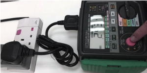
RCD testing has to be completed every three months, and documented, to remain in compliance. There is a test button on the device that has to be pressed to determine if the switch is working correctly. It is working properly if the power goes off. If the power does not go off, an electrician has to be called to re-test the switch, repair it, or replace it. It is strongly recommended that all homeowners, even those not selling the property have the devices installed for safety. The cost of installing residual current devices is nominal, especially compared to the safety of family members. In order to remain compliant to the standard, you will need to comply with the above test intervals in the section above.
One of the most common problems that we see in our country is that everyone is busy and it’s very easy to miss these dates and not be compliant with the standards. We can help you by taking care of this responsibility for you. The Carelabs team will send reminders of your RCD renewal coming due, several weeks before the renewal is due, to ensure you are always compliant at your premises.
Why Test Residual Current Devices?
Some electrical equipments and old wiring may have a normal small amount of earth leakage which can trip a RCD. Earth leakage increases with each additional electrical appliance that is plugged in, and if RCD keeps tripping out it may be an overloaded circuit. Any faults we recommend that you have your wiring and appliances checked by an electrician to ascertain the fault if a RCD keeps tripping.
The majority of electrical fatalities could have been prevented by the use of a properly installed RCD, and regular testing to ensure they are working correctly. RCD’s also protect against fire caused by faults in appliance, tools and wiring. If these faults go undetected they could cause a fire or personal injury. RCD’s provide a means of early fault detection.
Thermal Scanners is able to carry out all your RCD Testing requirements and upon completion, issues you with a Comprehensive Report and Compliance Certificate. If maintained correctly an RCD can not only help to prevent fire due to appliance or wiring faults, they save lives. Thermal Scanners help clients to ensure their RCD’s are compliant and tested in line with the UAE Standards.
What is Done During Testing of RCD?
RCDs must be tested. The requirements are stated in the following Regulations:
- The effectiveness of the RCD must be verified by a test simulating an appropriate fault condition and independent of any test facility, or test button, incorporated in the device (Regulation 713-13-01)
- Where an RCD of 30mA provides supplementary protection the operating time must not exceed 40 ms at a residual current of 5 I∆n. (Regulation 412-06-02 refers)
Tests are made on the load side of the RCD between the phase conductor of the protected circuit and the associated cpc. Any load or appliances should be disconnected prior to testing. RCD test instruments require a few milliamperes to operate; this is normally obtained from the phase and neutral of the circuit under test. When testing a three-phase RCD protecting a three-wire circuit, the instrument’s neutral is required to be connected to earth. This means that the test current will be increased by the instrument supply current and will cause some devices to operate during the 50% test, possibly indicating an incorrect operating time. Under this circumstance it is necessary to check the operating parameters of the RCD with the manufacturer before failing the RCD.
The RCD Testing Requirements indicate that a manager is required to test each device every three months. To conduct these tests, they must present the test button found on the residual current device. The RCD Testing results determine if the device is worked correctly. After each test, the manager must reset the device by pressing the appropriate button.
If at any time the test indicates that it isn’t operating properly, the manager must order a new device and shut down power to the location. They must tag and lock the device in the location in which it is used. This notifies workers of an existing issue and prevents them from using any connections running to it.
How are RCDs Tested?
The wiring regulations require the residual device providing additional protection to disconnect within 40 milliseconds when tested at 5 times the current they are designed to operate within normal circumstances. This is something electricians test using calibrated equipment and not something the homeowner can do. It is one of the tests carried out during an electrical inspection and confirms if the RCD would disconnect in the necessary time to prevent shock. Other tests confirm the device(s) are not oversensitive that would leave you without power unnecessarily. If you are not sure when the rcds within your installation have been tested, get in touch to make an appointment for me to test them for you. When RCD tests are carried out, it will trip the RCD and disconnect the circuit that it protects, so any electrical equipment will need to be turned off prior to RCD Testing being carried out.
Each RCD Test only takes approximately 5 minutes for each RCD. We suggest that RCD Testing is carried out after hours, before the office opens, or you will need to advise your staff that the power will be disrupted for each circuit, and that there computers will need to be turned off.
All electrical equipment needs to be turned off when RCD Testing is carried out.
Operating Time Test
Performed by an electrician, this test measures how long the RCD takes to trip, indicating whether it is fast enough be effective.
Push-button Test on RCDs
The push-button test is to ensure that the RCD will trip when there is an earth leakage, and break the electrical circuit protecting the individual from suffering an electric shock, or electrocution. When you press the test button, and the RCD has detected an imbalance, the on/off switch will jump to the “off” position. The test button will only test the RCD if an electricity supply is connected. This test should be performed daily or before each time you use the RCD – whichever is the longer. However it is not particularly accurate and should never be relied on as a reliable assessment of the RCD working correctly. The “trip time” test using the “applied current” method is a far more accurate means of testing RCDs and is a required test under AS/NZS 3760.
Trip Time Test
It measures the actual trip time and must be performed with equipment able to measure this to within +/- 8 ms (0.008 of a second).This is a simple test that can be performed by the user, to determine that the RCD’s tripping mechanism is working.
Portable RCDs
Portable RCDs requires the use of an isolation transformer to carry out operating time test.
Follow these simple steps to ensure your RCDs are operating correctly:
- Plug a small lamp into a power point and make sure it works. Leave it turned on.
- Make sure that electricity is connected to the property and the main switch is in the “on” position. The lamp should be on.
- Turn off all electronic equipment (computers and televisions) etc.
- Push the test button on each RCD. Do not hold your finger on the test button. The RCD should operate (turn off). If it does not operate, it must be checked by an electrical contractor.
- After pushing the test button and the RCDs have turned off check that the small lamp is now off. Also check that all the lights and power points do not operate. To do this, plug the small lamp into all the power points and turn the power point on. If the lamp turns on, a licensed electrical contractor must be engaged to correct the wiring.
- When finished testing, turn the RCDs back on and check that the lamp works when plugged into a power point.
Benefits of RCD Testing
A tested RCD can help put your mind at ease when it comes to the safety of your workers. RCD testing performed by a qualified professional can ensure that your RCDs have no faults in them and can be relied upon to function when needed. Some other benefits of RCD testing are:
- Compliance with safety standards
- Cost savings
- Early detection of faults
RELAY COORDINATION STUDY

Relay coordination study is a well-known fact that the power system is not completely free from failures/faults. The key here is to mitigate the consequences during the event of faults. Damage of equipment during a fault can be reduced by quickly isolating the faulty portion from rest of healthy system. The objective of relay coordination study is to determine optimum settings for protection devices such that protection system isolates the minimum possible faulty portion at the earliest possible in order to ensure the reliable power supply for the healthy system. The optimum settings ensure required sensitivity and selectivity that protect workers from harm as well. The software’s used for protection coordination study is ETAP. The relay coordination study involves protection devices from various manufacturers such as Siemens, ABB/Hitachi, GE, Schneider and so on.
WHY RELAY COORDINATION STUDY?
- To determine the optimum settings for protective devices in the system such as relays, releases and breakers etc in order to ensure that proper coordination is achieved.
- To analyze time coordination curves (TCC) to verify the coordination between upstream and downstream protection devices including fuses.
- To check the sequence of operation of protection devices for various operating configurations.
- To find out the fault clearing time.
- To verify the protection coordination of existing plant especially when there is a change in the network connectivity or source fault level.
- To generate calculation and finalize the unit protection settings of generator, line, cable, transformer, motor, reactor and capacitor banks.
- As an input for the calculation of incident energy in Arc Flash Studies.
HOW RELAY COORDINATION STUDY ? (METHODOLOGY)
- Collection of inputs (SLD, equipment parameters – Voltage kV rating, Power MVA rating, Impedance, System fault level, X/R ratio, relay details, protection schematics etc.)
- Modelling in study software.
- Carry out the short circuit simulations for various system configurations (normal and contingency configuration)
- Generating TCC curves and determine the characteristics and optimum settings
- Verification of sequence of operation for different types of faults (3 Ph, SLG, L-L, L-L-N) at various locations.
- Generating relay setting tables/charts, relay settings soft file (parameterization) file.
- Submission of detailed report.
- Presentation of study findings.
OUTCOMES OF RELAY COORDINATION STUDY
- Detailed report explaining the input data, system configuration, observations and recommendations
- Fault currents at various buses and branches in the system.
- Relay setting charts/tables with optimum settings
- Time coordination curves
- Sequence of operation
- Relay setting soft file
- Input to Arc Flash Study
The main objective of protection coordination study is to isolate the faulty portion as quick as possible to minimize the severity of damage to the faulted portion and causing unnecessary damage to the healthy part of the system.
Protection coordination is the selection and setting of protective devices in order to isolate only the faulted portion of the system.
A proper protection coordination is an essential ingredient of a well-designed electrical protection system.
In the planning stage of a power system network, the design engineer should endeavor to frame a protection system that is very simple and also ensures safety, reliability, easy maintenance and economic considerations.
Relay coordination begins from the farthest downstream device and coordination must exist with all upstream protective equipment up to the utility’s last protection device or the plant’s main protection device.
The time current characteristics curve generated for each protection device must be set in order to have proper coordination with the upstream protection equipment and strike a perfect balance between equipment damage and service continuity.
Protection coordination focuses on obtaining selectivity to minimize the extent of equipment shutdown in case of a fault.
ARC FLASH STUDY

Arc flash study is very crucial in power systems. An arc flash is a phenomenon where a flash-over of electric current leaves its intended path and travels through the air from one conductor to another, or to ground. The results are often violent and when a human is in close proximity to the arc flash, serious injury and even death can occur. Arc flash can be caused by many things including: Dust, Dropping tools, Accidental touching, Condensation, Material failure, Corrosion, Faulty Installation.
The factors to determine the severity of an arc flash injury are Proximity of the worker to the hazard, Temperature, fault current and Time for circuit to break. The main objective of an arc flash study is to identify and analyze high risk arc flash areas in your electrical power system with greater flexibility by simulating and evaluating various mitigation methods in arc flash study.
The National Fire Protection Association (NFPA) has developed specific approach boundaries designed to protect employees while working on or near energized equipment. These boundaries are
- Flash Protection Boundary (outer boundary)
- Limited Approach
- Restricted Approach
- Prohibited Approach (inner boundary)
The software’s used for arc flash study is ETAP and DigSilentPowerfactory.
WHY ARC FLASH STUDY?

- To determine maximum incident energyat MV and LV switchgear
- To establish the Arc flash boundary limit based on the arc fault current and fault clearing time.
- To specify the hazard / risk category
- To recommend suitable PPE for the safety of workers.
- To generate suitable danger and warning labels.
HOW ARC FLASH STUDY? (METHODOLOGY)
- Collection of inputs (SLD, equipment parameters – Voltage kV rating, Power MVA rating, Impedance, System fault level, X/R ratio, protection settings).
- Check the electrode configuration of the panel based on IEEE 1584 such as VCB, VCBB, HCB, VOA, HOA
- Modelling in study software.
- Determining the bolted fault current and performing short circuit studies at each switch-gear for the worst scenario.
- Determine the arc fault current.
- Determine the duration of arc fault current based on protection settings/relay coordination.
- Determine the incident energy for each switch-gearat the working distance and suitable PPE.
- Generating danger and warning labels.
- Submission of detailed report including labels.
OUTCOMES OF ARC FLASH STUDY
- Detailed report explaining the input data, system configuration, observations and recommendations
- Fault currents at various buses and branches in the system.
- Maximum incident energy at MV and LV switchgear.
- Arc flash boundary limit.
- Recommendation on suitable PPE
- Danger and warning labels with necessary safety information
STEPS TO CONDUCT AN ARC FLASH STUDY
An arc flash study is a comprehensive analysis of a facility’s electrical system to identify potential hazards associated with arc flashes, and to recommend safety measures that can be taken to mitigate these hazards. The following steps are typically involved in performing an arc flash study:
- Gathering data:The first step is to gather information about the electrical system, such as single-line diagrams, equipment ratings, and fault current and protection settings. This information is used to create a detailed model of the electrical system.
- Modeling the electrical system:Using Power System Simulation software (ETAP), the electrical system is modeled in detail, including all electrical components, protective devices, and cables. This model is used to calculate the magnitude of fault currents that can flow through the system in various fault scenarios.
- Identifying potential arc flash hazards:Based on the fault current calculations, potential arc flash hazards are identified, including the arc flash boundary, incident energy, and personal protective equipment (PPE) requirements.
- Recommending mitigation measures:Based on the hazard analysis, the study team may recommend various mitigation measures, such as protective relaying and coordination, equipment upgrades, arc-resistant switchgear, and labeling requirements. The goal is to reduce the likelihood of an arc flash event and minimize the severity of the event if one does occur.
- Documenting the results:The study team typically prepares a comprehensive report documenting the results of the arc flash study, including recommendations for mitigation measures, arc flash hazard labels, and PPE requirements.
- Ongoing maintenance:Once the study is complete, it is important to maintain the electrical system and update the study as changes are made to the system, such as adding or removing equipment, or changing protective device settings. This ensures that the study remains accurate and up-to-date.
It’s important to stay up-to-date with the latest industry standards and guidelines, IEEE 1584-2018, which provides updated methods for calculating arc flash hazards in AC and DC systems.
REFERENCE STANDARDS
- NFPA70E, “Standard for electrical safety in the workplace”,
- IEEE Std 1584, “IEEE Guide for performing Arc flash hazard calculation”,
LOAD FLOW STUDY

Load flow study is the quintessential study as it aids in proper planning, design, and operation of generation, transmission, and distribution networks. The results of the study provide detailed insight into the steady-state performance under different operating conditions. Load flow is the basis for several other types of studies such as short-circuit, stability, motor starting, and harmonic, and protection studies as it brings out the initial steady-state behavior of the system.
Results of the study will be of great help in identifying the suitable operating conditions and in identifying the abnormalities such as equipment overloading, excessive voltage drop, poor power factor, and power loss conditions. Most importantly the analysis assists in the proper selection of continuous rating of equipment and in spotting out the need for voltage regulation devices and power factor correction devices.
This study can be carried out using ETAP, DIg SILENT Power Factory and PSS/E.
WHY LOAD FLOW STUDY?
- Toobtain the voltage magnitudes and angle, real reactive power value, current, power losses, voltage drop, power factor, etc.
- To identify the loading of equipment under various operating scenarios. (Example: Minimum and maximum load variation, grid voltage variation, tie-breaker closed, transformer, transmission line, and generator outage conditions)
- To identify the need for voltage regulating devices, power factor correction devices,
- To properly select taps for transformer and voltage set points for generator and inverter.
- To select the continuous rating of the equipment.
HOW TO PERFORM LOAD FLOW STUDY?
- Collection of inputs (SLD, Electrical data-sheetsof all equipment, and FAT reports (if available)
- Modelling the system in software
- Finalizing the study case scenarios (Scenarios will consider the system configuration changes, Grid voltage variations, loading variations, and other scenarios requested by the client)
- Carrying out simulation
- Submission of a detailed report
- Presentation of study findings
OUTCOMES OF LOAD FLOW STUDY
- Detailed report explaining the input data, study cases, observations and recommendations
- Presentation to easily spot out abnormal conditions like voltage limit violations, overloading conditions, and improper continuous rating selections.
- Proposing applicable solutions to address the issues. (Example – Power factor correction devices, Reactive power support devices)
- Base simulation model for short-circuit, stability, motor starting, and harmonic, and protection studies.
REFERENCE
1.IEEE 399-1997 – IEEE Recommended Practice for Industrial and Commercial Power Systems Analysis
2.IEEE 3002.2-2018 – IEEE Recommended Practice for Conducting Load-Flow Studies and Analysis of Industrial and Commercial Power Systems